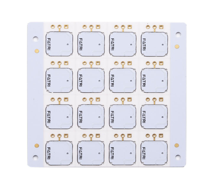
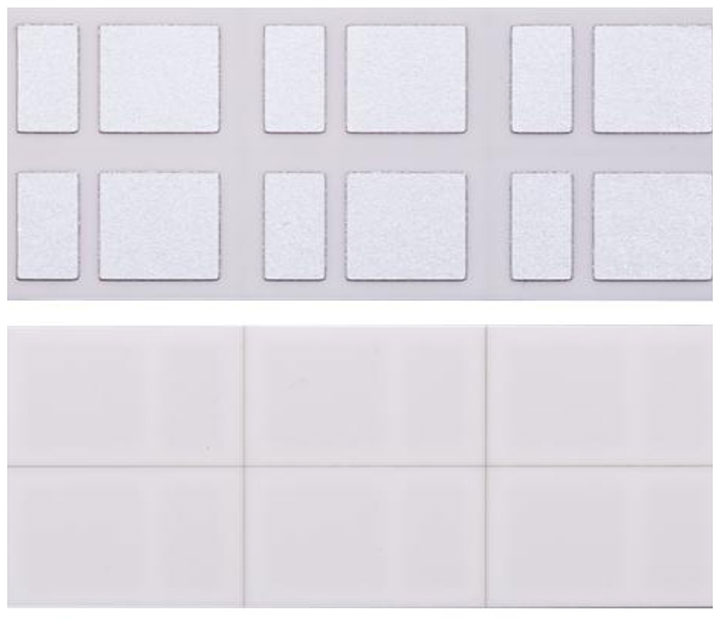
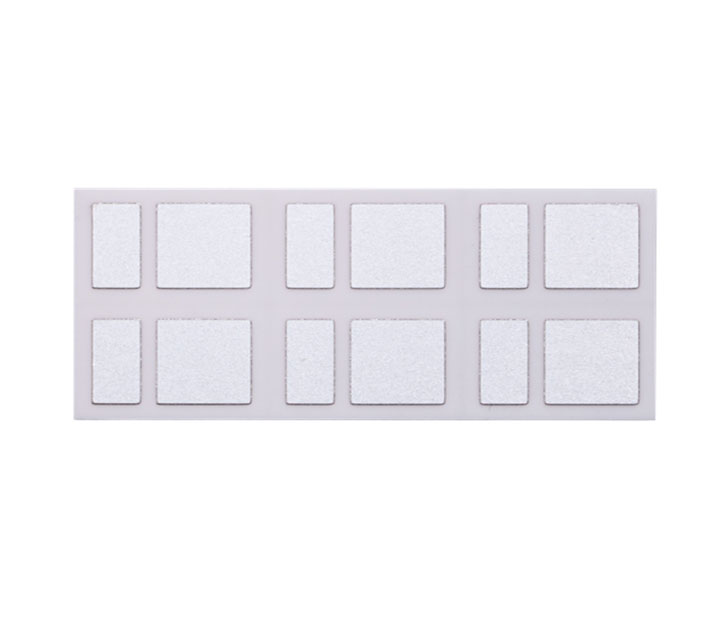
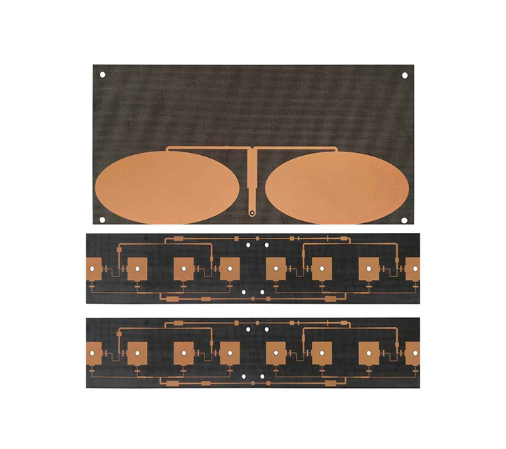
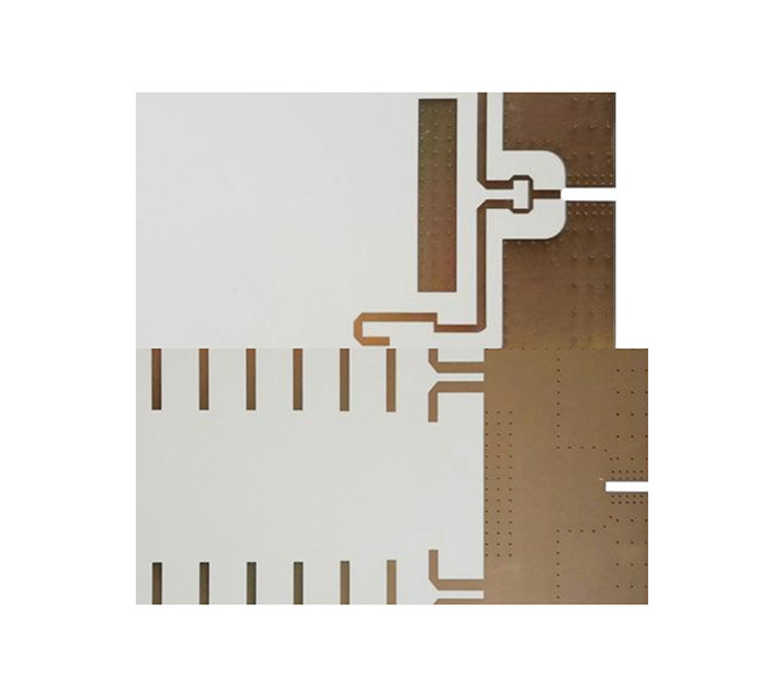
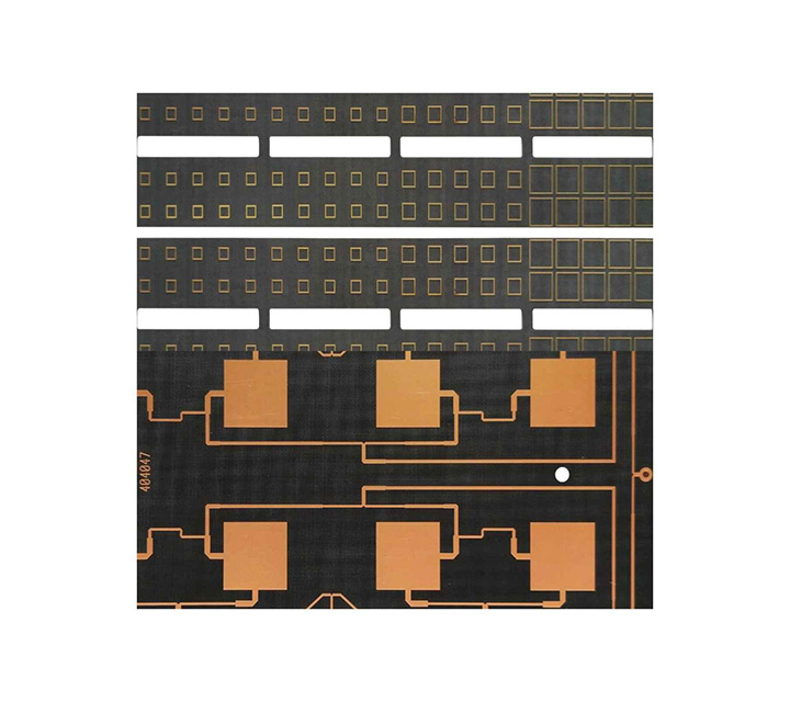
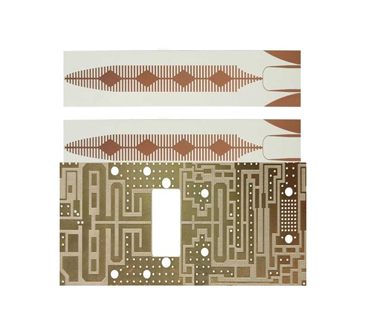
Common Ceramic Substrate PCB Board Introduction
Ceramic substrate PCB refers to a special process board in which copper foil is directly bonded to the surface of an alumina (Al2O3) or aluminum nitride (AlN) ceramic substrate (single or double-sided) at high temperature. The made ultra-thin composite substrate has excellent electrical insulation performance, high thermal conductivity, excellent solderability and high adhesion strength, and can etch various patterns like a PCB board, with a large current carrying capacity ability. Therefore, ceramic substrates have become the basic materials for high-power power electronic circuit structure technology and interconnection technology.
The advent of ceramic substrate PCB products has opened up new developments in the heat dissipation application industry. Due to the heat dissipation characteristics of ceramic substrates, coupled with the advantages of high heat dissipation, low thermal resistance, long life, and withstand voltage, with the improvement of production technology and equipment, products The accelerated rationalization of prices has expanded the application fields of the LED industry, such as indicator lights for home appliances, car lights, street lights, and large outdoor billboards. The successful development of ceramic substrates provides better services for indoor lighting and outdoor lighting products, making the LED industry a broader market in the future.
Applications for Ceramic Substrate PCB
◆ High-power power semiconductor modules; semiconductor refrigerators, electronic heaters; radio frequency power control circuits, power mixing circuits.
◆Intelligent power components; high frequency switching power supply, solid state relay.
◆Automotive electronics, aerospace and military electronic components.
◆Solar panel components; telecommunications special switches, receiving systems; industrial electronics such as lasers.
The Necessity of Using Ceramic Printed Circuit Boards
Ceramic Printed Circuit boards are actually made of electronic ceramic materials and can be made into various shapes. Among them, ceramic circuit boards have the most prominent characteristics of high temperature resistance and high electrical insulation performance, and have the advantages of low dielectric constant, low dielectric loss, high thermal conductivity, good chemical stability, and similar thermal expansion coefficients of components. Ceramic printed circuit boards are produced using laser rapid activated metallization technology LAM technology. Used in LED fields, high-power semiconductor modules, semiconductor coolers, electronic heaters, power control circuits, power hybrid circuits, intelligent power components, high-frequency switching power supplies, solid-state relays, automotive electronics, communications, aerospace and military electronic components.
Different from traditional FR-4 (glass fiber), ceramic material has good high-frequency performance and electrical performance, and has high thermal conductivity, chemical stability and thermal stability. Ideal encapsulation material for producing large scale integrated circuits and power electronic modules.
Main advantages:
1. Higher thermal conductivity
2. More matching coefficient of thermal expansion
3. A harder, lower resistance metal film alumina ceramic circuit board
4. The base material has good solderability and high service temperature.
5. Good insulation
6. Low frequency loss
7. Assembled with high density
8. Does not contain organic components, is resistant to cosmic rays, has high aerospace reliability and long service life
9. The copper layer does not contain an oxide layer and can be used for a long time in a reducing atmosphere.
Advantage of the Ceramic Substrate PCB
◆The thermal expansion coefficient of the ceramic substrate is close to the silicon chip, which can save the transition layer Mo sheet, save labor, save materials, and reduce costs;
◆Reduce solder layer, reduce thermal resistance, reduce voids, and improve yield;
◆Under the same current carrying capacity, the line width of 0.3mm thick copper foil is only 10% of that of ordinary printed circuit boards;
◆ Excellent thermal conductivity makes the package of the chip very compact, thus greatly increasing the power density and improving the reliability of the system and device;
◆ Ultra-thin (0.25mm) ceramic substrate can replace BeO, no environmental toxicity problem;
◆Large carrying capacity, 100A current continuously passes through the 1mm wide and 0.3mm thick copper body, and the temperature rise is about 17°C; 100A current continuously passes through the 2mm wide and 0.3mm thick copper body, the temperature rise is only about 5°C;
◆Low thermal resistance, the thermal resistance of a 10×10mm ceramic substrate is 0.31K/W for a 0.63mm thick ceramic substrate, 0.19K/W for a 0.38mm thick ceramic substrate, and 0.25mm thick ceramic substrate The thermal resistance is 0.14K/W.
◆ High insulation withstand voltage ensures personal safety and equipment protection.
◆ New packaging and assembly methods can be realized to make the product highly integrated and smaller in size.
performance requirements
Why Choose HSX
Top Ceramic substrate material resources, so that your products win at the root
Ceramic substrate is a kind of special pcb board, which has good thermal conductivity, insulation performance, and high dielectric constant, and is widely used in terminal products in the field of heat dissipation. Commonly used ceramic base materials include alumina, aluminum nitride, zirconia, ZTA, silicon nitride, silicon carbide, etc.
Leading process capability to meet high Ceramic Substrate PCB
manufacturing needs
- Max. thickness to diameter ratio 10:1 Max. copper thickness 6OZ Max. working board size 2000x610mm
- The thinnest 4-layer board 0.33mm The smallest hole 0.10mm
- Minimum line width/line spacing 3mil/3mil
- Commonly used ceramic base materials include alumina, aluminum nitride, zirconia, ZTA, silicon nitride, silicon carbide, etc.
What is the difference between ceramics, high frequency and ordinary PCB boards?
First. The difference between ceramic substrate and pcb board
1. Different materials. The ceramic substrate is an inorganic material, and the core is aluminum oxide or aluminum nitride; ordinary pcb boards use FR4 glass fiber boards, which are organic materials. Ordinary pcb boards can be laminated in multiple layers. Ceramic multilayer circuit boards are dominated by LTCC. The ceramic multilayer process currently being developed by United Multilayer Circuit Board Co., Ltd. is different from the traditional method. The new technology of magnetron sputtering is used to complete the metallization. A layer of ceramic dielectric is grown on the ceramic circuit board, and then re-metallized on this layer of dielectric to make the second layer of circuit.
2. The performance and application of ceramic substrates are different. The thermal conductivity of ceramic substrates far exceeds that of ordinary PCB boards. The thermal conductivity of alumina ceramics is ≧25W/(m·K), and the thermal conductivity of aluminum nitride ceramics is ≧170W/(m·K). They are used in industries that require greater heat dissipation , such as high-power LED lighting, high-power modules, high-frequency communication, track power supply, etc.; the thermal expansion coefficient of ceramic substrates is more compatible with silicon wafers, and the product stability is higher. Ordinary PCB boards are widely used, mostly on private commercial products.
Second, the difference between ceramic substrate and high frequency board
1. Different materials. The ceramic substrate is made of aluminum oxide or aluminum nitride, and the high-frequency board is mostly made of Rogers, Yalong, PTFE, etc., with low dielectric constant and fast high-frequency communication.
2. The performance is different. Ceramic substrates are widely used in refrigeration chips and systems, high-power modules, automotive electronics and other fields. High-frequency PCB boards are mainly used in high-frequency communication fields, aviation, high-end consumer electronics, etc.
3. In the field of high-frequency communication that involves heat dissipation requirements, ceramic substrates and high-frequency PCB boards are usually required to be combined, such as high-frequency ceramic pcbs.
PCB acceptance criteria
- IPC-A-600G standard (PCB conformity standard);
- GJB326A-96(military standard);
- IPC-6018A (high frequency board acceptance standards)
- Implementation of quality PDCA cycle process, continuous improvement of product performance imported from the United States Diane ion chromatography tester (DIONEXICS-900) and temperature cycle inspection equipment to ensure high reliability and stability of the product.
Why Choose HSX
Top high-frequency material resources, so that your products win at the root
The factory always has imported and domestic plates with dielectric constants ranging from 2.2 to 10.6
- High frequency materials: Rogers/Rogers, taconic/taikangli, Arlon, Isola, F4BM/Wangling, PTFE/Teflon, TP-2, etc., with dielectric constants ranging from 2.2 to 10.6.
- Rogers series: Rogers RO4350B, RO4003C, RT5880, RT5870, ro3003, ro3010, RO4730, RT6006, RT6010, etc.
Leading process capability to meet high frequency PCB manufacturing needs
- Max. thickness to diameter ratio 10:1 Max. copper thickness 6OZ Max. working board size 2000x610mm
- The thinnest 4-layer board 0.33mm The smallest hole 0.10mm
- Minimum line width/line spacing 3mil/3mil
- Proven hybrid technology: ROGERS/Rogers+FR4,FR4+PTFE,FR4+408HR,ceramic+FR4 etc.
Experienced
PCB high-frequency board samples + small and medium batch, more than ten years of experience, skilled in PCB high-frequency board expertise
Products are: FR4 glass fiber board double-sided multilayer circuit board / high frequency board / high frequency circuit board / high frequency mixed laminate / mixed media laminate / F4B high frequency board / microwave RF board / high frequency microwave board, etc., the power splitter, coupler, combiner, power amplifier, dry amplifier, base station, RF antenna, 4G antenna used in the high frequency circuit board has professional production experience
PCB acceptance criteria
- IPC-A-600G standard (PCB conformity standard);
- GJB326A-96(military standard);
- IPC-6018A (high frequency board acceptance standards)
- Implementation of quality PDCA cycle process, continuous improvement of product performance imported from the United States Diane ion chromatography tester (DIONEXICS-900) and temperature cycle inspection equipment to ensure high reliability and stability of the product.
HSX’s Ceramic Substrate PCB Capabilities
Feature
Capability
Quality Grade
Standard IPC 2
Number of Layers
1-2 layers
Material
Alumina, Aluminum Nitride, Zirconia, ZTA, Silicon Nitride, Silicon Carbide, etc.
Board Size
Min 5mm x 5mm | Max 500mm x 745mm
Board Thickness
0.2mm – 4.0mm
Copper Weight(Finished)
0.5oz – 2oz
Min Tracing/Spacing
3mil/3mil
Solder Mask Color
Green, White, Blue, Black, Red, Yellow…
Silkscreen Color
White, Black, Yellow…
Surface Finish
Electroless nickel/immersion gold (ENIG) – RoHS
Immersion silver – RoHS
Immersion tin – RoHS
Min Annular Ring
0.1mm
Min Drilling Hole Diameter
0.15mm
Other Techniques
Peelable solder mask
Gold fingers
Carbon oil
Countersink holes
Do You Need Assistance or Have a Question?
We Provide Quality Service, Good Price for PCBs.
Ceramic Substrate PCB
Product Information
Ceramic Substrate PCB refers to a special process board in which copper foil is directly bonded to the surface of an alumina (Al2O3) or aluminum nitride (AlN) ceramic substrate (single or double-sided) at high temperature. The made ultra-thin composite substrate has excellent electrical insulation performance, high thermal conductivity, excellent solderability and high adhesion strength, and can etch various patterns like a PCB board, with a large current carrying capacity ability. Therefore, ceramic substrates have become the basic materials for high-power power electronic circuit structure technology and interconnection technology.
The advent of ceramic substrate PCB products has opened up new developments in the heat dissipation application industry. Due to the heat dissipation characteristics of ceramic substrates, coupled with the advantages of high heat dissipation, low thermal resistance, long life, and withstand voltage, with the improvement of production technology and equipment, products The accelerated rationalization of prices has expanded the application fields of the LED industry, such as indicator lights for home appliances, car lights, street lights, and large outdoor billboards. The successful development of ceramic substrates provides better services for indoor lighting and outdoor lighting products, making the LED industry a broader market in the future.
Applications for Ceramic Substrate PCB
Ceramic Printed Circuit Boards are actually made of electronic ceramic materials and can be made into various shapes. Among them, ceramic circuit boards have the most prominent characteristics of high temperature resistance and high electrical insulation performance, and have the advantages of low dielectric constant, low dielectric loss, high thermal conductivity, good chemical stability, and similar thermal expansion coefficients of components. Ceramic printed circuit boards are produced using laser rapid activated metallization technology LAM technology. Used in LED fields, high-power semiconductor modules, semiconductor coolers, electronic heaters, power control circuits, power hybrid circuits, intelligent power components, high-frequency switching power supplies, solid-state relays, automotive electronics, communications, aerospace and military electronic components.
Different from traditional FR-4 (glass fiber), ceramic material has good high-frequency performance and electrical performance, and has high thermal conductivity, chemical stability and thermal stability. Ideal encapsulation material for producing large scale integrated circuits and power electronic modules.
Main advantages:
- Higher thermal conductivity
- More matching coefficient of thermal expansion
- A harder, lower resistance metal film alumina ceramic circuit board
- The base material has good solderability and high service temperature.
- Good insulation
- Low frequency loss
- Assembled with high density
- Does not contain organic components, is resistant to cosmic rays, has high aerospace reliability and long service life
- The copper layer does not contain an oxide layer and can be used for a long time in a reducing atmosphere.
The Necessity of Using High Frequency PCB
Ceramic Printed Circuit boards are actually made of electronic ceramic materials and can be made into various shapes. Among them, ceramic circuit boards have the most prominent characteristics of high temperature resistance and high electrical insulation performance, and have the advantages of low dielectric constant, low dielectric loss, high thermal conductivity, good chemical stability, and similar thermal expansion coefficients of components. Ceramic printed circuit boards are produced using laser rapid activated metallization technology LAM technology. Used in LED fields, high-power semiconductor modules, semiconductor coolers, electronic heaters, power control circuits, power hybrid circuits, intelligent power components, high-frequency switching power supplies, solid-state relays, automotive electronics, communications, aerospace and military electronic components.
Different from traditional FR-4 (glass fiber), ceramic material has good high-frequency performance and electrical performance, and has high thermal conductivity, chemical stability and thermal stability. Ideal encapsulation material for producing large scale integrated circuits and power electronic modules.
Main advantages:
1. Higher thermal conductivity
2. More matching coefficient of thermal expansion
3. A harder, lower resistance metal film alumina ceramic circuit board
4. The base material has good solderability and high service temperature.
5. Good insulation
6. Low frequency loss
7. Assembled with high density
8. Does not contain organic components, is resistant to cosmic rays, has high aerospace reliability and long service life
9. The copper layer does not contain an oxide layer and can be used for a long time in a reducing atmosphere.
Advantage of the Ceramic Substrate PCB
◆The thermal expansion coefficient of the ceramic substrate is close to the silicon chip, which can save the transition layer Mo sheet, save labor, save materials, and reduce costs;
◆Reduce solder layer, reduce thermal resistance, reduce voids, and improve yield;
◆Under the same current carrying capacity, the line width of 0.3mm thick copper foil is only 10% of that of ordinary printed circuit boards;
◆ Excellent thermal conductivity makes the package of the chip very compact, thus greatly increasing the power density and improving the reliability of the system and device;
◆ Ultra-thin (0.25mm) ceramic substrate can replace BeO, no environmental toxicity problem;
◆Large carrying capacity, 100A current continuously passes through the 1mm wide and 0.3mm thick copper body, and the temperature rise is about 17°C; 100A current continuously passes through the 2mm wide and 0.3mm thick copper body, the temperature rise is only about 5°C;
◆Low thermal resistance, the thermal resistance of a 10×10mm ceramic substrate is 0.31K/W for a 0.63mm thick ceramic substrate, 0.19K/W for a 0.38mm thick ceramic substrate, and 0.25mm thick ceramic substrate The thermal resistance is 0.14K/W.
◆ High insulation withstand voltage ensures personal safety and equipment protection.
◆ New packaging and assembly methods can be realized to make the product highly integrated and smaller in size.
performance requirements
Why Choose HSX
Top Ceramic substrate material resources, so that your products win at the root
Ceramic substrate is a kind of special pcb board, which has good thermal conductivity, insulation performance, and high dielectric constant, and is widely used in terminal products in the field of heat dissipation. Commonly used ceramic base materials include alumina, aluminum nitride, zirconia, ZTA, silicon nitride, silicon carbide, etc.
Leading process capability to meet high Ceramic Substrate PCB
manufacturing needs
- Max. thickness to diameter ratio 10:1 Max. copper thickness 6OZ Max. working board size 2000x610mm
- The thinnest 4-layer board 0.33mm The smallest hole 0.10mm
- Minimum line width/line spacing 3mil/3mil
- Commonly used ceramic base materials include alumina, aluminum nitride, zirconia, ZTA, silicon nitride, silicon carbide, etc.
What is the difference between ceramics, high frequency and ordinary PCB boards?
First. The difference between ceramic substrate and pcb board
1. Different materials. The ceramic substrate is an inorganic material, and the core is aluminum oxide or aluminum nitride; ordinary pcb boards use FR4 glass fiber boards, which are organic materials. Ordinary pcb boards can be laminated in multiple layers. Ceramic multilayer circuit boards are dominated by LTCC. The ceramic multilayer process currently being developed by United Multilayer Circuit Board Co., Ltd. is different from the traditional method. The new technology of magnetron sputtering is used to complete the metallization. A layer of ceramic dielectric is grown on the ceramic circuit board, and then re-metallized on this layer of dielectric to make the second layer of circuit.
2. The performance and application of ceramic substrates are different. The thermal conductivity of ceramic substrates far exceeds that of ordinary PCB boards. The thermal conductivity of alumina ceramics is ≧25W/(m·K), and the thermal conductivity of aluminum nitride ceramics is ≧170W/(m·K). They are used in industries that require greater heat dissipation , such as high-power LED lighting, high-power modules, high-frequency communication, track power supply, etc.; the thermal expansion coefficient of ceramic substrates is more compatible with silicon wafers, and the product stability is higher. Ordinary PCB boards are widely used, mostly on private commercial products.
Second, the difference between ceramic substrate and high frequency board
1. Different materials. The ceramic substrate is made of aluminum oxide or aluminum nitride, and the high-frequency board is mostly made of Rogers, Yalong, PTFE, etc., with low dielectric constant and fast high-frequency communication.
2. The performance is different. Ceramic substrates are widely used in refrigeration chips and systems, high-power modules, automotive electronics and other fields. High-frequency PCB boards are mainly used in high-frequency communication fields, aviation, high-end consumer electronics, etc.
3. In the field of high-frequency communication that involves heat dissipation requirements, ceramic substrates and high-frequency PCB boards are usually required to be combined, such as high-frequency ceramic pcbs.
PCB acceptance criteria
- IPC-A-600G standard (PCB conformity standard);
- GJB326A-96(military standard);
- IPC-6018A (high frequency board acceptance standards)
- Implementation of quality PDCA cycle process, continuous improvement of product performance imported from the United States Diane ion chromatography tester (DIONEXICS-900) and temperature cycle inspection equipment to ensure high reliability and stability of the product.
Why Choose HSX
Top high-frequency material resources, so that your products win at the root
The factory always has imported and domestic plates with dielectric constants ranging from 2.2 to 10.6
- High frequency materials: Rogers/Rogers, taconic/taikangli, Arlon, Isola, F4BM/Wangling, PTFE/Teflon, TP-2, etc., with dielectric constants ranging from 2.2 to 10.6.
- Rogers series: Rogers RO4350B, RO4003C, RT5880, RT5870, ro3003, ro3010, RO4730, RT6006, RT6010, etc.
Leading process capability to meet high frequency PCB manufacturing needs
- Max. thickness to diameter ratio 10:1 Max. copper thickness 6OZ Max. working board size 2000x610mm
- The thinnest 4-layer board 0.33mm The smallest hole 0.10mm
- Minimum line width/line spacing 3mil/3mil
- Proven hybrid technology: ROGERS/Rogers+FR4,FR4+PTFE,FR4+408HR,ceramic+FR4 etc.
Experienced
PCB high-frequency board samples + small and medium batch, more than ten years of experience, skilled in PCB high-frequency board expertise
Products are: FR4 glass fiber board double-sided multilayer circuit board / high frequency board / high frequency circuit board / high frequency mixed laminate / mixed media laminate / F4B high frequency board / microwave RF board / high frequency microwave board, etc., the power splitter, coupler, combiner, power amplifier, dry amplifier, base station, RF antenna, 4G antenna used in the high frequency circuit board has professional production experience
PCB acceptance criteria
- IPC-A-600G standard (PCB conformity standard);
- GJB326A-96(military standard);
- IPC-6018A (high frequency board acceptance standards)
- Implementation of quality PDCA cycle process, continuous improvement of product performance imported from the United States Diane ion chromatography tester (DIONEXICS-900) and temperature cycle inspection equipment to ensure high reliability and stability of the product.


