Product Information
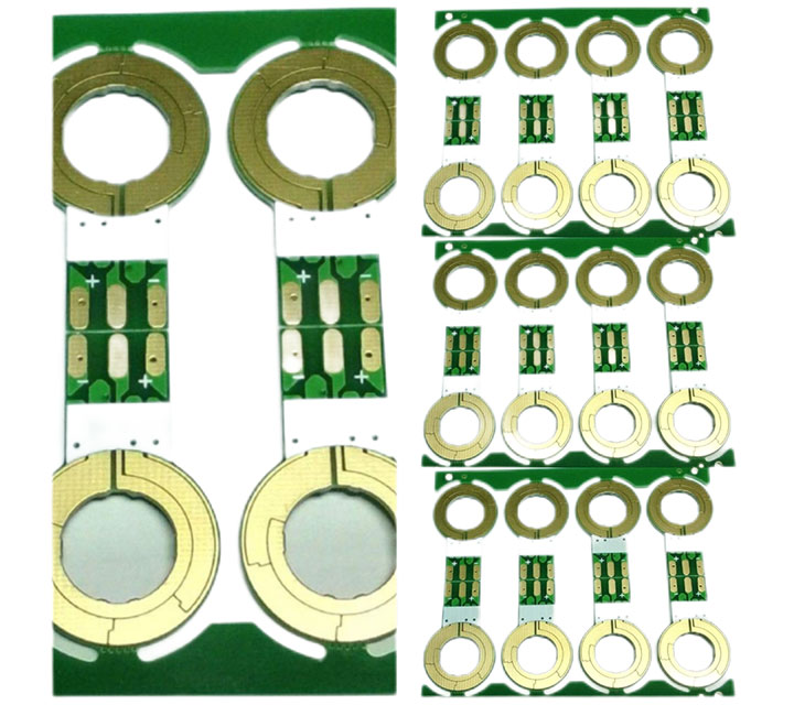
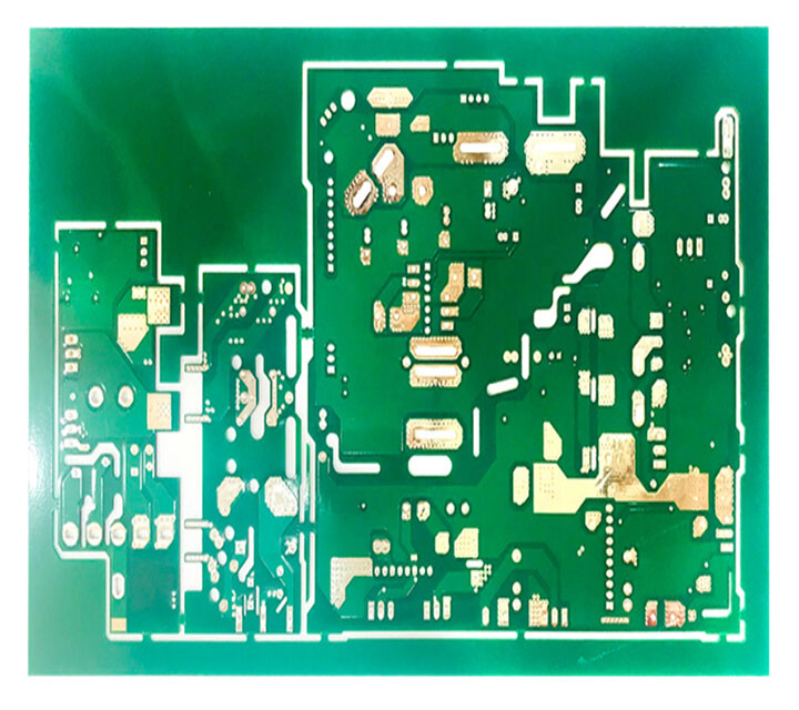
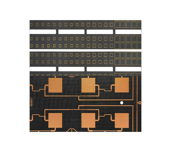
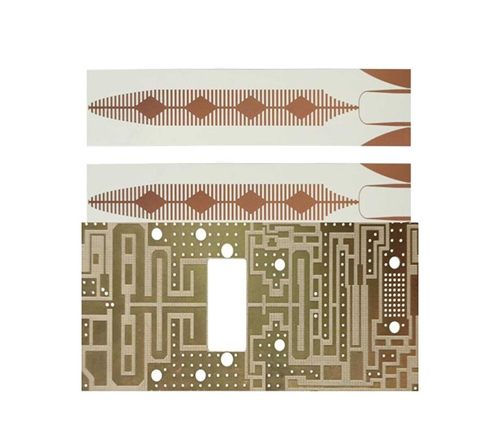
Heavy Copper PCB is a layer of copper foil bonded on the glass epoxy substrate of the printed circuit board. When the copper thickness is ≥ 20z, it is defined as thick copper board. In PCB proofing, Heavy Copper PCB plate is a special process, which has certain technical threshold and operation difficulty, and the cost is relatively expensive. area. Thick copper plates are widely used in various household appliances, high-tech products, medical and other electronic equipment.
Why use Heavy Copper PCB?
Heavy Copper PCB contain more than three ounces of copper material per square foot and are used to carry high current loads. You will find copper material thicknesses used in such PCBs in the range of 105 – 400 µm. Additionally, Rigid-flex PCB are able to maintain dissipation at high temperatures while providing stronger connections. Additionally, this thermal management feature ensures that thick copper PCBs are free from thermal stress.
What are the performance and advantages of Heavy Copper PCB?
A Heavy Copper PCB is a layer of copper foil bonded to the glass epoxy substrate of the printed circuit board. The thickness of this copper foil can be divided into many different types, such as 18um, 35um, 55um and 70um. The thickness varies. The applications are also very different. Heavy Copper PCB plates are mainly used in power-saving products, especially electronic products that require higher voltage and current. So what are the advantages and performance of Heavy Copper PCB?
- Heavy Copper PCB have a wide range of applications and are used in almost all metal materials used in construction. Thick copper sheets have the best elongation properties and are ideal for architectural moldings. Heavy Copper PCB are not limited by processing temperatures. It can blow oxygen at high melting point, but not brittle at low temperature. It is also fireproof and is a non-combustible material. Copper PCBs form a strong, non-toxic bell-like protective layer even in highly corrosive atmospheres.
- Unique advantages of thick copper pcb circuit board: Heavy Copper PCB not only has excellent strength and processing adaptability, but also can be applied to various processes, such as unit wall, flat lock system, standing edge snap system, Bem system, rainwater drainage system etc. It can also accommodate the various processing requirements these systems require and, since Heavy Copper PCB boards are affordable, they are often sold at hardware stores. Affordable Heavy Copper PCB are not only used in industrial buildings, even in life, workers who understand electrical technology can purchase and modify them as needed.
- The application of Heavy Copper PCB is almost everywhere, and its application fields are very wide, including various household appliances, high-tech products, military, medical and other electronic equipment. The application of thick-hole copper plate makes the circuit board of electronic equipment products have a longer service life, and at the same time greatly helps to simplify the size of electronic equipment. Today, the number of manufacturers producing Heavy Copper PCB in the market is gradually increasing.
Why Choose HSX
Top Heavy Copper PCB plate material resources, so that your products win at the root
- Thick copper board is a layer of copper foil bonded on the glass epoxy substrate of the printed circuit board. When the copper thickness is ≥ 20z, it is defined as thick copper board. In PCB proofing, thick copper plate is a special process, which has certain technical threshold and operation difficulty, and the cost is relatively expensive. Thick copper plates are widely used in various household appliances, high-tech products, medical and other electronic equipment
Leading process capability to meet Heavy Copper PCB manufacturing needs
- Max. thickness to diameter ratio 10:1 Max. copper thickness 6OZ Max. working board size 2000x610mm
- The thinnest 4-layer board 0.33mm The smallest hole 0.10mm
- Minimum line width/line spacing 3mil/3mil
- Proven hybrid technology: ROGERS/Rogers+FR4,FR4+PTFE,FR4+408HR,ceramic+FR4 etc.
Experienced
- PCB Heavy Copper PCB samples + small and medium batch, more than ten years of experience, skilled in PCB Heavy Copper PCB board expertise
- Products are: FR4 glass fiber board double-sided multilayer circuit board / Heavy Copper PCB / Heavy Copper PCB mixed laminate / mixed media laminate / F4B Heavy Copper PCB / microwave RF board / Heavy Copper PCB microwave board, etc., the power splitter, coupler, combiner, power amplifier, dry amplifier, base station, RF antenna, 4G antenna used in the Heavy Copper PCB has professional production experience
PCB acceptance criteria
- IPC-A-600G standard (PCB conformity standard);
- GJB326A-96(military standard);
- IPC-6018A (Heavy Copper PCB acceptance standards)
- Implementation of quality PDCA cycle process, continuous improvement of product performance imported from the United States Diane ion chromatography tester (DIONEXICS-900) and temperature cycle inspection equipment to ensure high reliability and stability of the product.
Why Choose HSX
Top high-frequency material resources, so that your products win at the root
The factory always has imported and domestic plates with dielectric constants ranging from 2.2 to 10.6
- High frequency materials: Rogers/Rogers, taconic/taikangli, Arlon, Isola, F4BM/Wangling, PTFE/Teflon, TP-2, etc., with dielectric constants ranging from 2.2 to 10.6.
- Rogers series: Rogers RO4350B, RO4003C, RT5880, RT5870, ro3003, ro3010, RO4730, RT6006, RT6010, etc.
Leading process capability to meet high frequency PCB manufacturing needs
- Max. thickness to diameter ratio 10:1 Max. copper thickness 6OZ Max. working board size 2000x610mm
- The thinnest 4-layer board 0.33mm The smallest hole 0.10mm
- Minimum line width/line spacing 3mil/3mil
- Proven hybrid technology: ROGERS/Rogers+FR4,FR4+PTFE,FR4+408HR,ceramic+FR4 etc.
Experienced
PCB high-frequency board samples + small and medium batch, more than ten years of experience, skilled in PCB high-frequency board expertise
Products are: FR4 glass fiber board double-sided multilayer circuit board / high frequency board / high frequency circuit board / high frequency mixed laminate / mixed media laminate / F4B high frequency board / microwave RF board / high frequency microwave board, etc., the power splitter, coupler, combiner, power amplifier, dry amplifier, base station, RF antenna, 4G antenna used in the high frequency circuit board has professional production experience
PCB acceptance criteria
- IPC-A-600G standard (PCB conformity standard);
- GJB326A-96(military standard);
- IPC-6018A (high frequency board acceptance standards)
- Implementation of quality PDCA cycle process, continuous improvement of product performance imported from the United States Diane ion chromatography tester (DIONEXICS-900) and temperature cycle inspection equipment to ensure high reliability and stability of the product.
HSX’s High Frequency PCB Capabilities
Feature
Capability
Quality Grade
Standard IPC 2
Number of Layers
2- 24layers
Material
ROGERS, TACONIC, ARLON, FR4,
Board Size
Min 5mm x 5mm | Max 500mm x 745mm
Board Thickness
0.2mm – 4.0mm
Copper Weight(Finished)
0.5oz – 2oz
Min Tracing/Spacing
3mil/3mil
Solder Mask Color
Green, White, Blue, Black, Red, Yellow…
Silkscreen Color
White, Black, Yellow…
Surface Finish
Electroless nickel/immersion gold (ENIG) – RoHS
Immersion silver – RoHS
Immersion tin – RoHS
Min Annular Ring
0.1mm
Min Drilling Hole Diameter
0.15mm
Other Techniques
Peelable solder mask
Gold fingers
Carbon oil
Countersink holes
Do You Need Assistance or Have a Question?
We Provide Quality Service, Good Price for PCBs.
High Frequency PCB
Product Information
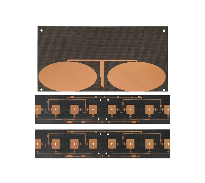
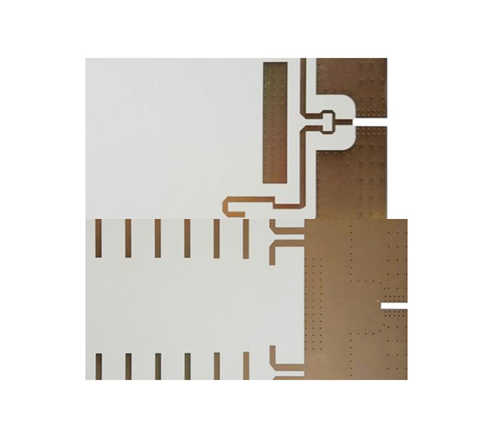
A high frequency printed circuit board, whether it’s rigid or flex, offers faster signal flow rates and a frequency range of up to 100 GHz. It’s important to note that there are numerous materials designed to operate at high frequency levels. HF PCBs are defined by lower dielectric constant (Dk), lower dissipation factor (Df), and low levels of thermal expansion. They are used regularly for HDI technology. They are also used extensively in high speed communications, telecommunications, and RF microwave technology.
Depending on the parameters, the HF signal is reflected on the circuit board, which means that the impedance (dynamic resistance) changes relative to the transmitting component. To avoid such capacitive effects, all parameters must be specified accurately and implemented with the highest level of process control.
Applications for High Frequency PCB
High frequency printed circuit boardis are widely used for special signal transmission between objects. It operates from 500MHz to 2GHz and is right for mobile, microwave, RF and high-speed design applications. With the increasing complexity of electronic components and switches, faster signal flow and better transmission frequency are needed. High frequency PCB can play a really important role.Due to the short rise time of the pulse in electronic components, it is necessary to consider the conductor width as an electronic component in HF technology.
The Necessity of Using High Frequency PCB
High-frequency PCBs usually provide a frequency range from 500MHz to 2 GHz, which can meet the needs of high-speed PCB designs, microwave, radio frequency, and mobile applications. When the frequency is above 1 GHz, we can define it as high frequency.
- The complexity of electronic components and switches is continually increasing nowadays and need faster signal flow rates. So, higher transmission frequencies are required. High-frequency PCBs help a lot when integrating special signal requirements into electronic components and products with advantages like high efficiency, and fast speed, lower attenuation, and constant dielectric properties.
- High Frequency (HF) PCB is used to transmit electromagnetic waves in the frequency of GHz with minimal loses in the variety of applications, including mobile, microwave, radio frequency (RF) and high-speed design applications. Hence, printed circuit boards with some specific characteristics are used to transmit these electromagnetic waves. Several parameters are taken into considerations while designing a PCB for high frequency applications.
- A high frequency PCB can meet your needs when incorporating a special signal requirement into your electronic devices and products. These higher transmission frequencies are capable of supporting the faster signal flow rates that are a necessity in today’s increasingly complex electronic switches and other components.
Why Choose HSX
Top high-frequency material resources, so that your products win at the root
The factory always has imported and domestic plates with dielectric constants ranging from 2.2 to 10.6
- High frequency materials: Rogers/Rogers, taconic/taikangli, Arlon, Isola, F4BM/Wangling, PTFE/Teflon, TP-2, etc., with dielectric constants ranging from 2.2 to 10.6.
- Rogers series: Rogers RO4350B, RO4003C, RT5880, RT5870, ro3003, ro3010, RO4730, RT6006, RT6010, etc.
Leading process capability to meet high frequency PCB manufacturing needs
- Max. thickness to diameter ratio 10:1 Max. copper thickness 6OZ Max. working board size 2000x610mm
- The thinnest 4-layer board 0.33mm The smallest hole 0.10mm
- Minimum line width/line spacing 3mil/3mil
- Proven hybrid technology: ROGERS/Rogers+FR4,FR4+PTFE,FR4+408HR,ceramic+FR4 etc.
Experienced
- PCB high-frequency board samples + small and medium batch, more than ten years of experience, skilled in PCB high-frequency board expertise
- Products are: FR4 glass fiber board double-sided multilayer circuit board / high frequency board / high frequency circuit board / high frequency mixed laminate / mixed media laminate / F4B high frequency board / microwave RF board / high frequency microwave board, etc., the power splitter, coupler, combiner, power amplifier, dry amplifier, base station, RF antenna, 4G antenna used in the high frequency circuit board has professional production experience
PCB acceptance criteria
- IPC-A-600G standard (PCB conformity standard);
- GJB326A-96(military standard);
- IPC-6018A (high frequency board acceptance standards)
- Implementation of quality PDCA cycle process, continuous improvement of product performance imported from the United States Diane ion chromatography tester (DIONEXICS-900) and temperature cycle inspection equipment to ensure high reliability and stability of the product.
Why Choose HSX
Top high-frequency material resources, so that your products win at the root
The factory always has imported and domestic plates with dielectric constants ranging from 2.2 to 10.6
- High frequency materials: Rogers/Rogers, taconic/taikangli, Arlon, Isola, F4BM/Wangling, PTFE/Teflon, TP-2, etc., with dielectric constants ranging from 2.2 to 10.6.
- Rogers series: Rogers RO4350B, RO4003C, RT5880, RT5870, ro3003, ro3010, RO4730, RT6006, RT6010, etc.
Leading process capability to meet high frequency PCB manufacturing needs
- Max. thickness to diameter ratio 10:1 Max. copper thickness 6OZ Max. working board size 2000x610mm
- The thinnest 4-layer board 0.33mm The smallest hole 0.10mm
- Minimum line width/line spacing 3mil/3mil
- Proven hybrid technology: ROGERS/Rogers+FR4,FR4+PTFE,FR4+408HR,ceramic+FR4 etc.
Experienced
PCB high-frequency board samples + small and medium batch, more than ten years of experience, skilled in PCB high-frequency board expertise
Products are: FR4 glass fiber board double-sided multilayer circuit board / high frequency board / high frequency circuit board / high frequency mixed laminate / mixed media laminate / F4B high frequency board / microwave RF board / high frequency microwave board, etc., the power splitter, coupler, combiner, power amplifier, dry amplifier, base station, RF antenna, 4G antenna used in the high frequency circuit board has professional production experience
PCB acceptance criteria
- IPC-A-600G standard (PCB conformity standard);
- GJB326A-96(military standard);
- IPC-6018A (high frequency board acceptance standards)
- Implementation of quality PDCA cycle process, continuous improvement of product performance imported from the United States Diane ion chromatography tester (DIONEXICS-900) and temperature cycle inspection equipment to ensure high reliability and stability of the product.


